2. Networking service: OpenStack Neutron
This section explains the main concepts behind the OpenStack Networking service (Neutron) and it will help you perform simple actions in order to get familiar with this service.
2.1. What is Neutron?
Neutron is an OpenStack project to provide “Network connectivity as a Service (NaaS)”. The OpenStack Networking service (neutron) provides an API that allows users to build rich networking topologies, set up and define network connectivity, configure advanced network policies and addressing in the cloud.
OpenStack Networking handles the creation and management of a virtual networking infrastructure, including networks, switches, subnets, and routers for devices managed by the OpenStack Compute service (nova). Advanced services such as firewalls or virtual private network (VPN) can also be used but are not currently available on this cloud.
OpenStack Networking integrates with various OpenStack components:
- OpenStack Identity service (keystone) is used for authentication and authorization of API requests.
- OpenStack Compute service (nova) is used to plug each virtual NIC on the VM into a particular network.
- OpenStack Dashboard (horizon) is used by administrators and project users to create and manage network services through a web-based graphical interface.
2.1.1. Basic concepts
OpenStack Networking (neutron) manages all networking facets for the Virtual Networking Infrastructure (VNI) and the access layer aspects of the Physical Networking Infrastructure (PNI) in OpenStack.
Networking provides networks, subnets, and routers as object abstractions. Each abstraction has functionality that mimics its physical counterpart: networks contain subnets, and routers route traffic between different subnets and networks.
Any given Networking set up has at least one external network. Unlike the other networks, the external network or provider network is not merely a virtually defined network. Instead, it represents a view into a slice of the physical, external network accessible outside OpenStack. IP addresses on the external network are accessible by anybody physically on the outside network. In our OpenStack, different kind of provider networks have been defined to serve to different uses cases:
- The CUDN Public network allows public traffic from the Internet. This is the provider network you want to use whether you are going to create a public web server or general service.
- The CUDN Private network only allows internal traffic from the University of Cambridge domain. This is a more restricted network that could be applied to management networks or services restricted to the University domain.
Both networks are illustrated in (Fig. 2.3) as CUDN-Internet (public facing) and CUDN-Private (internal).
In addition to external networks, a project will have one or more private, internal networks. These software-defined networks, called tenant networks or project networks in OpenStack, connect directly to the VMs. Only the VMs on any given internal network, or those on subnets connected through interfaces to a Neutron router, can access VMs connected to that network directly. The (Fig. 2.3) shows an example of a tenant network (Service and Management networks). Notice these elements remain unconnected and there are still missing elements, like routers and instances. In further sections, we will see a complete example that put all these elements working together.
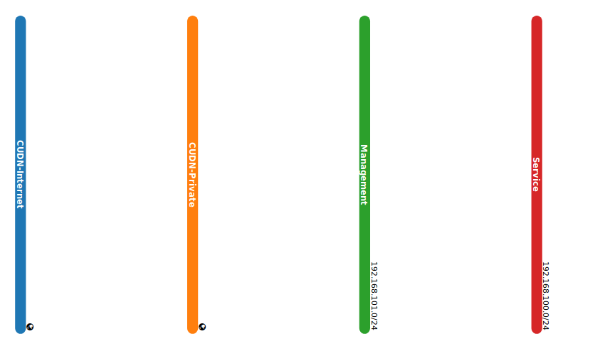
Fig. 2.3 Provider and Tenant networks.
For the outside network to access VMs, and vice versa, routers between the networks are needed. Each router has one gateway that is connected to an external network and one or more interfaces connected to internal networks. Like a physical router, subnets can access machines on other subnets that are connected to the same router, and machines can access the outside network through the gateway for the router.
Additionally, you can allocate IP addresses on external networks to ports on the internal network. Whenever something is connected to a subnet, that connection is called a port. You can associate external network IP addresses with ports to VMs. This way, entities on the outside network can access VMs.
Networking also supports security groups. Security groups enable administrators to define firewall rules in groups. A VM can belong to one or more security groups, and Networking applies the rules in those security groups to block or unblock ports, port ranges, or traffic types for that VM.
2.1.2. Main options
There are two important menus in OpenStack that will allow you to create and manage all required elements: the Network menu and Security and Access menu. The first one, Network (Project -> Network), presents all the options to create networks, subnets, and routers as follows:
- Network Topology: View the network topology. An example of what you can see in this section are (Fig. 2.3) and (Fig. 2.14).
- Networks: Create and manage public and private networks (Fig. 2.4). Here you will able a list with both tenant and provider networks, and whether they are externally accessible or not.
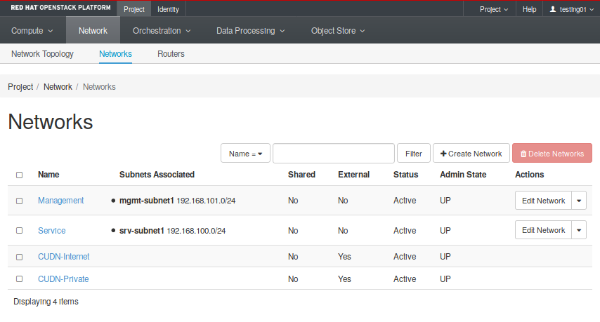
Fig. 2.4 Project -> Network -> Networks tab
- Routers: Create and manage routers. The Fig. 2.5 shows two different routers created, each one attached to a different external network.
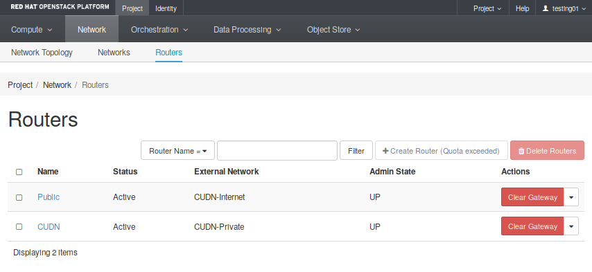
Fig. 2.5 Project -> Network -> Routers tab
On the other hand, the Security and Access menu controls (Compute -> Access and Security) all elements that allow you to control the access and security rules applied to the previous elements.
- Security Groups: Create and manage Security Groups and rules applied to them.
- Floating IPs: Create and manage public network addresses to attach to your virtual infrastructure.
Both menus tabs cases are illustrated in the following figures.
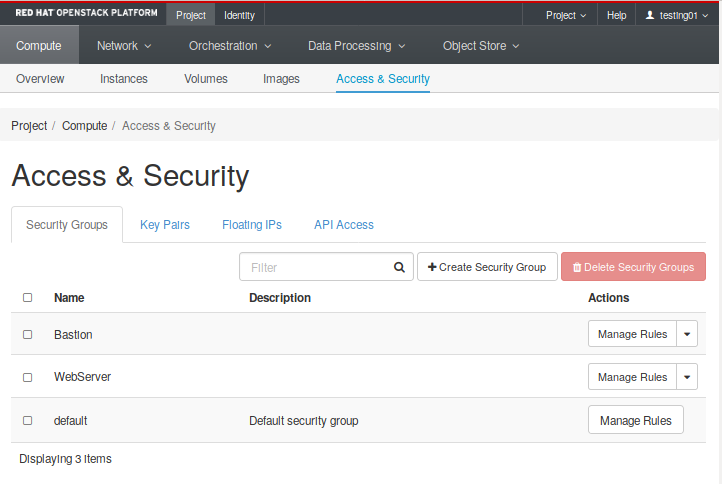

Regarding access. At the same level, there is also the Key Pair tab you can use to create and manage your SSH key pairs. The public part of an SSH key pair will be injected into an instance when it is created, allowing external access to the instance with its corresponding private half. For more information, see the next section.
2.2. Networking use cases
The OpenStack platform allows you to create complex network infrastructures with greater flexibility: you can easily create networks, routers, and connect each other using virtual network interfaces. However, it is essential to take into account some useful considerations before start designing the solution.
One important question to think about is the differences between Layer 2 and layer 3 networking. When designing your virtual network, you will need to anticipate where the majority of traffic is going to be sent. You have to take into account that network traffic moves faster within the same logical network, rather than between networks. This is because traffic between logical networks (using different subnets) needs to pass through a router, resulting in additional latency. Switching occurs at a lower level of the network (layer 2), so can function much quicker than the routing that occurs at layer 3. The preference should be to have as few hops as possible between systems that frequently communicate. You could perform easy tests using tools like mtr (my trace route) . This tool will show you both latency and numbers of hops between two VMs. In this example, you could observe there are two hops between these hosts because all traffic from 192.168.100.6 should pass through a router (192.168.100.1) to reach the host 192.168.101.15:
user@192.168.100.6:~$ mtr --report 192.168.101.15
HOST: frontend                    Loss%   Snt   Last   Avg  Best  Wrst StDev
  1.|-- 192.168.100.1              0.0%    10    0.4   0.5   0.3   1.3   0.0
  2.|-- 192.168.101.15             0.0%    10    0.9   1.3   0.6   6.2   1.6
Another important question about designing your network is how to define a multi-tier topology taken into account the previous point and still achieve the same functionality. Essentially, all tenant networks (and subnets) are exactly the same. Which makes them different are the set of interconnections defined (e.g connected to a provider network), routing tables, and security group rules. All these elements will enable you to build networking topologies that separate public traffic from accessing services in other internal components, e.g. to an internal service (LDAP) or DB layer.
The example shown at Fig. 2.6 presents a topology with two different tiers. A service network running a server (i.e. Web server), and another internal network (Management network) with an especial host (Bastion host), dedicated to administrative tasks.

Fig. 2.6 Example 1: Service layer and dedicated management network.
We can add more complexity to this example adding load balancing to scale out the service. However, we also need a well-defined group of security group rules to ensure isolation between both services, so different services are isolated from each other using Security Groups. As a result, the Load balancer will be the only public facing element and Web servers could only be directly accessed by the Load balancer (Fig. 2.7).

Fig. 2.7 Example 2: Service layer and dedicated management network. Diferent services are isolated from each other using Security Groups. Web servers are only accesible by the Load balancer.
Further, we could still introduce more complexity and create a secure back-end network for communication between all the servers and some internal service authentication service, file storage, or other components. This example (Fig. 2.8) shows three different layers:
- A service layer hosting different public facing servers
- The data layer with an internal database with direct connection to the web servers, but only accessible from both data and management networks.
- The management layer.
For more information about creating complex Virtual Network topologies with OpenStack, go to the Getting help section and contact us.

Fig. 2.8 Example 3: Multi-tier network application and management network topology.
2.3. Create your first network topology
This section introduces many of the network concepts that are discussed in the previous section. In this network layout, we assume that you are going to use the CUDN Public and Private networks as an external (public and internal) network provider networks.
At the end of this section, you will have created a complete networking topology using the OpenStack dashboard, following all necessary steps to create the service network to which the Web server node attach, as is present in the following diagram.
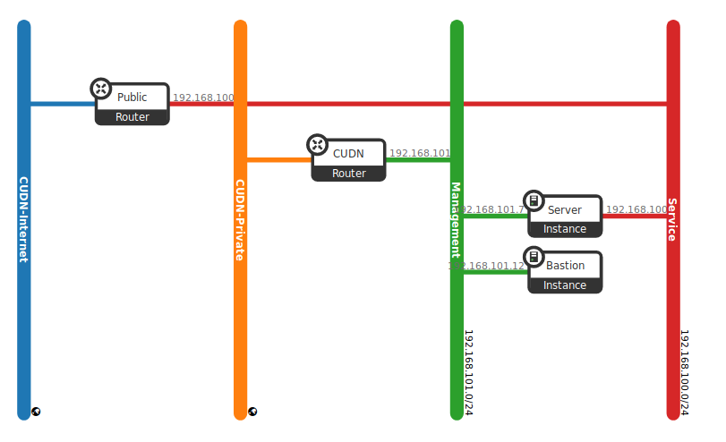
Fig. 2.9 Network topology example.
In this schema, web server instances will have their own Service network, which is accessible worldwide, by allocating floating IPs from the public network. Therefore, a service network to which the server nodes attach has been created. Also, a tenant router provides routing and external access for the server nodes using the CUDN Internet network, and floating IP addresses from this provider network are associated to the web server to facilitate external access.
You also need to create a management network to attach a Bastion host. This kind of hosts are mainly dedicated to performing administrative tasks, and they should have very restricted rules of access. In this case, we use a dedicated both provider network (CUDN Private) and router to attach this host later on.
2.3.1. Summary
A summary of the main goals we want to accomplish:
- We would like to deploy a new web service.
- We need a dedicated IP address to provide this service and it should be reachable worldwide.
- We also need a dedicated and secure management network with an IP address to provide access to a host used to perform administrative tasks in our service.
With the OpenStack dashboard, the workflow for creating the scenario proposed is as follows:
- Create a network and subnet for the web server (CDIR 192.168.100/24).
- Create a network and subnet for the bastion host (CDIR 192.168.101/24). This is the management network.
- Create a router for the Public service attached to the CUDN Internet network.
- Create a router for the management attached to the CUDN Private network.
- Allocate a floating IP address and assign it to the web server (IP 128.x.x.x).
- Allocate a floating IP address and assign it to the bastion host (IP 172.x.x.x).
Even though you can do this step later on creating the instances, you should think about all security rules we want to apply to this concrete scenario in advance. Doing it this way allows you to prevent security issues and create a good design that permits you to obtain all the functionality required. As best practice apply a rule of least privilege. You can read more about this here
2.3.2. Create networks and subnets
First of all, confirm that we have a public network by listing the networks our tenant has access to. You can see all networks going into the Project -> Network -> Networks tab. There you will find both CUDN networks (Fig. 2.10).
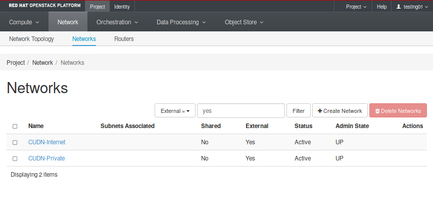
Fig. 2.10 Project -> Network -> Networks tab
Notice these networks have the External parameter set in “Yes”. That means they can be used to reach the Internet. Now it is time to create all required networks and subnets for both service and management layers. These steps will help you through the process of creating the service network:
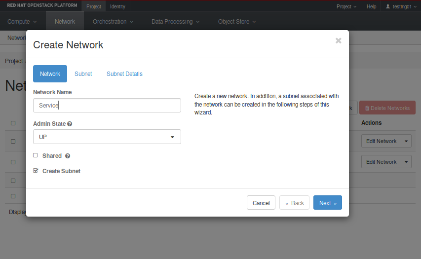
- First, click on “Create Network”
- Next, set name and description. In our example is “service” (see the first image on the left below).
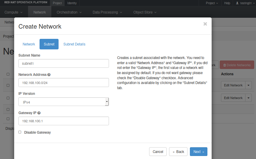
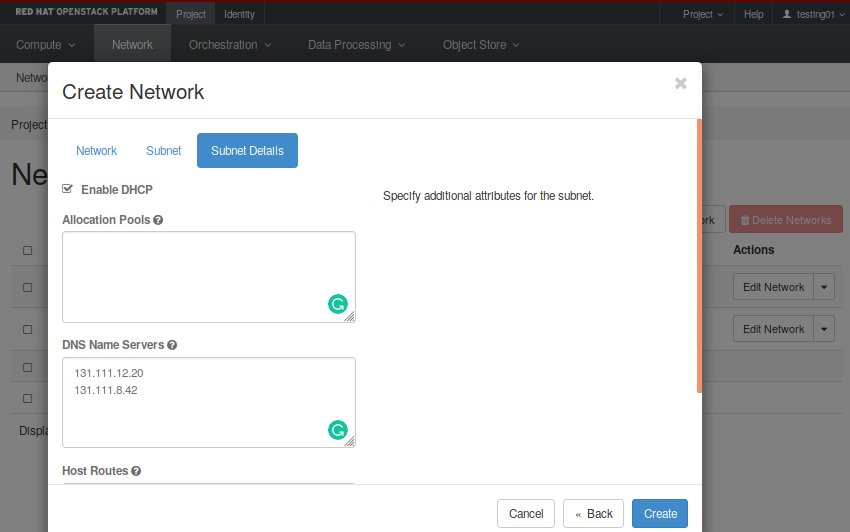
- You need to create a subnet inside this network. You must define the CDIR you want to use and set a name. You can leave the gateway address in blank, and Neutron will set it up by default. In our example, the network address is 192.168.100.0/24.
- Then, in the “Subnet Details” option, insert the “DNS Name Servers”, which in our case are 131.111.12.20 and 131.111.8.42. Also, ensure the “Enable DHCP” box is checked, so instances will receive a DHCP-assigned IP address in this subnet.
- Finally, click on “Create”.
Next, create a network and subnet for the management layer. The same steps can be applied to create this network, but using its own network address. If you click on the topology tab (Project -> Network -> Topology), you finally should be able to see all four networks created like in Fig. 2.11.
Fig. 2.11 Networks created after follow all required steps.
Now that you have got the networks created, go ahead to the Compute -> Access and Security -> Floating IPs and reserve a Floating IP to provide external connectivity for the web server. Repeat the same process in order to provide access to a future management host, but choosing the CUDN Private pool. In our example we have already reserved two floating IPs for our hosts (Fig. 2.12).
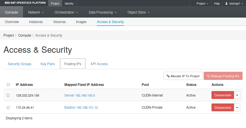
Fig. 2.12 Allocated floating IP addresses
Next video will help you to allocate a floating IP address.
Note
If you get the “No more IP addresses available on network” error, contact your cloud administrator. Floating IPs are a quota-ed resource.
2.3.3. Connecting to the Internet
Most instances require access to the Internet and, of course, a web server is not an exception. You need to allow traffic between the users and your web server, which means you need to add a router that connects your tenant network with the CUDN Internet network.
In a similar way, you need an isolated access from the CUDN Private network to your management network, so you also need to create a router between these two elements and connect them together by giving the private network allocated to management an interface on that router.
These steps will help you to create a router attached to your service network:
- First, go to the Project -> Network -> Routers menu and click on “Create Router”.
- Set a name for this router and select the network to be attached to. In this case we select the CUDN Internet network (Fig. 2.13).
- Now click on the router recently created, go to the interfaces tab and click on “Add interface”. Select the “service” subnet and click “Submit”. This will attach your router to the web service network.
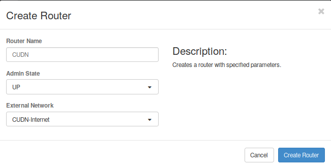
Fig. 2.13 Create a router.
Repeat the same step, now with the management network to allow access from the CUDN Private network to the management network.
After following all the steps, you should have obtained a topology similar to what can be seen in the Fig. 2.14.
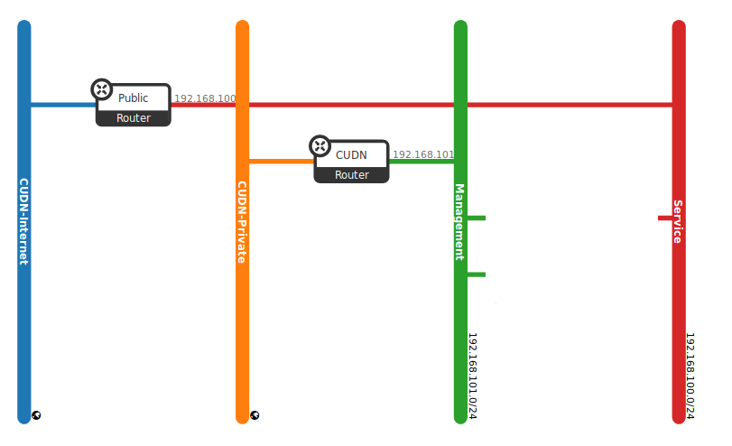
Fig. 2.14 Network topology. Please find this view in the Project -> Network -> Topology tab.
Note
If you cannot create more routers, bear in mind there is also a default quota for routers and may you want to ask for more.
Next video shows step-by-step how to create a private network, add a subnet, and attach a router to the CUDN Network.
2.3.4. Define security groups rules and rules
Last step is to define all security rules you need to apply in this scenario in order to provide the required functionality, but keeping your instances as secure as possible for unwanted traffic.
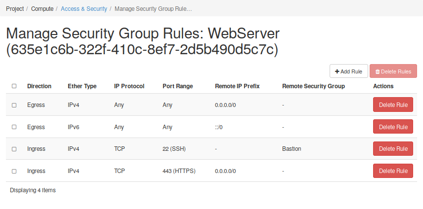
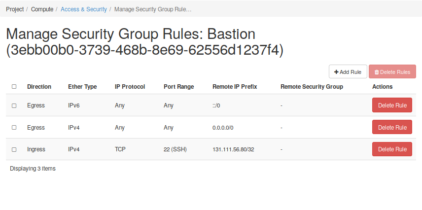
Go to the Security and Access menu and select the Security Groups tap. Here you will find a button to create a security group (SG). You should assign a name provide a description to this SG. Then, you will find a button which allows you to manage both Igress and Egress rules. In these cases it is often useful to think of Security Groups as security roles. The next figure Fig. 2.15 shows two different security groups, one for each compoment we will have in our infrastructure: one web server and one bastion host.
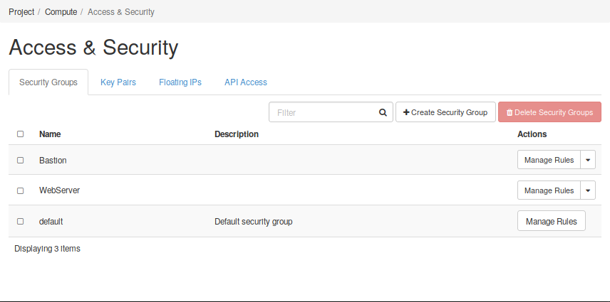
Fig. 2.15 Manage Security Groups
In the figures below, it can be seen that a set of rules has been created for each Security Group to define their roles. of the nodes, and each group of rules defines a role. In the first case, the web server must be reachable from any address (0.0.0.0) to the TCP 443 port. However, only the bastion host can be connected to by the SSH port of TCP 22. In the case of the bastion host, it can also only be accessed from a trusted host.
This is the end of this getting started with Neutron guide. You should now have an understading of how to create networks and subnets in OpenStack. You saw how to connect different networks using routers, and you have reserved floating IPs to allow external connectivity to a service deployed in the future. So, now that you have prepared the networking infrastructure, you can go ahead and boot all wanted instances on it. If you don’t know how to do it or you want to know more about the process, you can start reading the next sections. Ensure you use an appropriate flavor and image values for your services - see the next section to have more details.
Next video shows how to manage Security Groups rules using the Horizon dashboard.
2.4. Registration of DNS Names
After assigning a floating IP to an instance in order to give it external connectivity to the CUDN or global Internet, you will find that these floating IPs already have some human-unfriendly service DNS A records associated to them, e.g.
The floating 172.24.47.9 has an A record of 172-24-47-9.vss.cloud.private.cam.ac.uk.
Users may want to instead associate a human friendly DNS CNAME to their assigned floating IPs in front of their services running on instances, particularly they may want to assign CNAMEs that live in their home department’s University DNS management zones.
If this is the case, please send a support request to support@hpc.cam.ac.uk and the required modifications to the University DNS can be made.
2.5. Lab 2 - Creation of a network and subnet
Go to Creation of a network and subnet and follow the slides to start a hands-on work over this section.
- Lab overview slides
- Hands-on work